Teknik Resim (Drawing) Kesit Alma(Section) -5


Görünüşler üzerinde değişik kesit uygulamaları yapılabilir


1-Normal Kesit Alma 


View layout paletinden Section view seçilir Kesit düzlemi çizilir ve kesit görünüş istenen yere yerleştirilir. Filip direction kısmından bakış yönü değiştirilir.


2-Döndürülmüş Kesit Alma 


View layout paletinden Section view komutunun altındaki aligned seçilir Kesit düzlemi iki çizgi olarak çizilir ve kesit görünüş istenen yere yerleştirilir. Filip direction kısmından bakış yönü değiştirilir.


3-Kademeli Kesit Alma 


Kademeli kesitin gececeği çizgi normal çizgi ile çizilir çizginin tamamı seçilip View layout paletinden Section view seçilir seçilen çizgi seçilir ve kesit görünüş istenen yere yerleştirilir. Filip direction kısmından bakış yönü değiştirilir.

4-Kısmi Kesit Alma 


View layout paletinden Broken out section seçilir Spline eğrisi kullanılarak Kısmi kesidin alınacağı görünüş üzerinde kapalı bir şekil oluşturulur Depth kısmından kısmi kesidin derinliği girilir ve ok basılır.


Teknik Resim ( Drawing) Yüzey Şekil ve Konum Toleransları - 4

Yapım resimlerinde Standart görünüşler üzerinde Yüzey Şekil ve Konum Toleranasları da bulunmalıdır. Bu işlem programda şu şekilde yapılır Öncelikle Annotation paletindeki Datum Feature kullanılarak referans alınacak yüzey işaretlenir. Sonra aynı paletteki Geometrik tolerance seçilir ilgili kısımlar doldurulur. Ve tamam seçilmeden toleransın konulacağı yüzeye yerleştirilir.


Solidworks Mold Tools Araçları ile Kalıp Çıkarma

Solidworks Mold Tools Araçları ile Kalıp Çıkarma


Mold Tools

Draft Analysis

Kalıp çalışma yönüne göre, parçanın kalıptan çıkmasını kolaylaştırmak için gerekli yüzey açıları kontrol edilir, 

Scale

Parçanın malzemesi belirlenir ve çekme payı miktarı parça büyütülür.

Shut Off Surface

Parça üzerinde boşluklar kapatılır.


Parting Line

Kalıp ayrım çizgisinin yeri belirlenir, 

Parting Surface

Kalıp ayrım yüzeyi oluşturulur ve kalıp çıkartılır.

Tooling Split 

Oluşturulan dişi ve erkek kalıp iki ayrı parça olarak kaydedilir ve daha sonra kalıp setine yerleştirilerek kullanılır


Introduction to SOLIDWORKS Tutorial -1


<h1>Introduction to SOLIDWORKS</h1>


Introduction to SOLIDWORKS

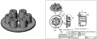
The Introduction to SOLIDWORKS lesson guides you through the creation of a part and a drawing. You create this part and drawing:


This lesson includes:
  • Creating base, boss, and cut features from sketches
  • Adding fillets to smooth edges
  • Creating a circular pattern
  • Adding drawing views
  • Adding centerlines, center marks, and dimensions to the drawing

My First Part


For your first part, you create the pressure plate shown below. A part is a 3D model made up of features.


You begin this lesson by creating a new part.


  • Click New  on the Standart toolbar.


If this is the first document you have created, the Units and Dimension Standard dialog box appears.

For Units, select MMGS(millimeter, gram, second)
For Dimension Standard select ANSI.
Click OK


The New SOLIDWORKS Documentdialog box appears.

  • Click Part.


  • Click OK

A new part window appears.

When toolbar buttons have an orange border, for example , you can click them in the tutorial window to flash the corresponding button in the SOLIDWORKS window.


Sketching the Circle


The first feature in the part is a cylinder extruded from a sketched circular profile.


  • Click Extrude Boss/ Base on the Features Toolbar.
    The Front, Top, and Right planes appear in the graphics area.

  • Move the pointer over the Top plane to highlight it, then click to select it.
    The display changes so that the plane is facing you. A sketch opens on the Top
  • Click Circle  
  • on the Sketch toolbar. The Circle PropertyManager opens in the left pane.
  • Move the pointer over the origin 

    The pointer changes to  . This indicates a coincident relation between the center of the circle and the origin.
  •  Click to place the center point on the origin.
    • Move the mouse and notice a preview of the circle dynamically follows the pointer.
    • Click to finish the circle and click in the PropertyManager.
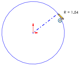
    The size of your sketch entities does not need to be exact. For example, this circle does not need to be 1.54. You later add dimensions to specify the size of sketch entities.